Audio Test File Generator Specifications
The goal was to produce a generator of audio frequency sine wave signals of the highest possible quality that may be used as a frequency standard for testing all components in the path of the signal. A very thorough specification follows, with the aim to increase the usefulness of the signal generator for sound engineers.
The sine wave generator
In the quest to create "the perfect wave", the floating point
calculations that produce the sine wave employ 80 bits of internal precision.
Each signal generated is a perfectly symmetrical series of whole waves so as to
end up with a negligible DC component. Whatever DC remains is removed,
so that for any given frequency of 10 seconds duration or less, the DC
level is guaranteed to be 0. In the case of 16 bit samples, dithering may
add a minuscule amount of DC. DC correction is not applied to signals of a duration greater than 10 seconds.
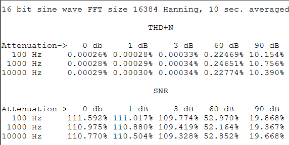
The following are details of distortion and
noise readings taken on 10 second files at 44100 samples per second. It should be
noted that these commonly used frequencies have significantly higher THD and noise than,
for example, most of the musical notes because of aliasing due to the fact that they
share a common denominator with the sampling rate. For example, a sine wave of C6 (1046.502261 Hz)
at 0 dB, averaged over a 10 second test file and under the same test setup, has a THD+N
of only 0.00011% and a SNR of about 114 dB. Compare that to the results below for 1000 Hz.
As a testament to the effectiveness of dithering, simply average that same 1046.502261 Hz (C6) signal
over 120 seconds and you will find the THD+N has now dropped to 0.00008% and SNR > 122 dB. (SNRs are for a bandwidth of 22kHz)
Each sine wave signal generated begins and ends with a smooth linear taper of exact multiples of the period to eliminate speaker pops and clicks. (See image above). The taper length depends on the duration of the signal requested, with the maximum duration set to approximately 0.01 seconds. The minimum taper length is equal to the period of the requested frequency. [Since version 1.06, the Audio Test File Generator has employed a raised cosine (Blackman half-windows) for the fade up/down to minimize distortion during fades.]
Signal duration is equal to exact multiples of the period at the requested frequency, such that they add up to at least the duration requested in seconds.
Minimum signal duration is limited to the nearest exact multiple of the period equal to or greater than 0.01 seconds, or the time it takes to play two whole waves at the requested frequency - whichever is greater. The maximum length depends on sample rate and bit width. For example, an hour long signal at 22050 samples per second, with 16 bit samples is well within the limit. A signal is ultimately limited by byte size of the resulting file to about 16 gigabytes.
Minimum frequency that can be generated is 10 Hz, and the maximum is the Nyquist limit (half the sample rate).
16 bit samples are converted at the desired attenuation from floating point to 32 bit samples and TPDF dithering is added to the lower 16 bits of each. This combination is then downshifted to the final 16 bit output sample size. A separate dithering signal is applied to each channel. (See images at bottom of page.)
In the case of 16 bit signals, to avoid saturation while allowing room for dithering or DC correction (should it be required), the initial maximum signal value is limited to a maximum amplitude of +/- 0x7FFD (32765). The final signal has a peak amplitude of -0.047 dB.
Maximum attenuation permitted is 90 dB for 16 bit signals, 138 dB for 24 bit signals, and 186 dB for 32 bit signals. If attenuation is applied, the signal level is calculated by dB = 20 x log10(peak amplitude). Attenuation is also calculated with the highest precision possible.
Files are generated in the form of stereo Window's RIFF PCM Wave format files. Each begins with a lead in of 512 samples of silence and a lead out of between 0 and 512 samples of silence (depending on how much room was left in the buffer).
The sweep wave generators
The sweep generators employ a swept sine wave function. In the case of the Linear Sweep, an equal phase delta is applied to each sample, whereas for the Logarithmic Sweep, a log base 2 function ensures that there are an equal number of samples per octave. The difference can be seen in an FFT of the averaged signal. The magnitudes of a linear sweep will draw a straight line across all bins within the sweep range, whereas the magnitudes of a logarithmic sweep will slope down to the right by 3 dB per octave. This is because when samples are all averaged together, each succeeding octave has half the number of samples per frequency delta than the previous, and therefore half the energy. This is only an illusion however, in the sense that as we hear each sample played, its amplitude is equal to all others and therefore the magnitude of the frequency component is also equal. The sweep generators do not employ DC correction. (Significant DC can accumulate in a sweep signal but attempts to remove it would result in unacceptable distortion.) It can sweep up or down. The minimum and maximum frequencies and attenuation values allowed are the same as for the sine wave generator. The minimum sweep duration is 0.1 seconds. Duration is rounded up to the nearest multiple of 128 samples. A linear taper of 128 samples is applied to the end of the signal. During taper down, the frequency is held at the ending frequency requested. The default setting sweeps through 6 octaves from C2 to C8.
The white noise generator
Since version 1.06 of the Audio Test File Generator a Gaussian noise generator for white noise was employed. The pseudo-random number generator employs the "Mother-Of-All" generator invented by George Marsaglia and provides an excellent even distribution. The code for this can be found at https://www.agner.org/random/. The overlaid Gaussian window is a codification of the Box-Muller transform in its basic form to provide a zero-centered normal distribution of the samples. The output was thoroughly tested to ensure uniform distribution with a Gaussian curve.
The pink noise generator
The pink noise generator employs an algorithm by Andrew Simper of Vellocet, a C++ implementation derived from the
code provided by the following people mainly from the music-dsp mailing list: Allan Herriman, James McCartney, Phil Burk and Paul Kellet and the web page by Robin Whittle: https://www.firstpr.com.au/dsp/pink-noise/.
Maximum signal level is nowhere near 0 dB, since considerable head room is given to ensure there can be no clipping. Determining the signal level of noise is problematic because of its random nature. However, if you employ attenuation you can be assured of accuracy of relative signal levels over the long term.
Its "peak" frequency is below 1 Hz, a thing you can verify by averaging a 120 second file using a very large FFT size.
Warning - pink noise contains frequencies below the range of hearing that may damage your speakers at very high levels. Turn down the bass if you want to pump up the sound, or watch your speaker cones for excessive movement.
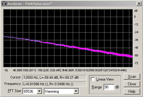
From Wikipedia: "Pink noise, also known as 1/f noise, is a signal or process with a frequency spectrum such that the power spectral density is proportional to the reciprocal of the frequency. There is equal energy in all octaves (or similar log bundles). In terms of power at a constant bandwidth, 1/f noise falls off at 3 dB per octave. At high enough frequencies 1/f noise is never dominant. (White noise is equal energy per hertz.) 1/f noise occurs in many physical, biological and economic systems. Below are images showing spectral views of the signals produced by the Audio Test Signal Generator."
Pink noise falls off at 3 dB per octave...
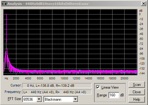
440 Hz sine wave without dithering...

Same signal with dithering applied...